Curing Material on an Aluminum Mandrel
Objective Heat a customer supplied aluminum cylinder to 80-120°C for a material curing application. More application notes
Processes
Processes: More
Processes: More

Industries:
Industries: More
Industries: More
Industries: More

Products:
Products: More
Services:
Services: More

Learn:
Learn: More
About:

2 min read
Brett Daly
12/12/22 7:15 AM

Induction heating uniformity issues can cause a variety of problems with part quality. We often see these issues because of irregular heating patterns due to unusual part shape or nontraditional heating requirements.
Here are six ways you can augment your induction coil design or heating process to address common heating uniformity problems.
Barber poling occurs when the high flux field adjacent to the coil turns produces a spiral pattern on the part.
To eliminate barber poling, rotate the workpiece during heating. For most short-duration hardening operations, rotational speeds producing at least 10 revolutions during the heating cycle are ideal.
When the coil extends over the end of a shaft-like part, a deeper pattern is produced on the end. To reduce this effect, the coil must be brought to a point even with or slightly lower than the end of the shaft.
The same condition exists in the heating of a disk or a wheel. The depth of heating will be greater at the ends than in the middle if the coil overlaps the part.
The coil can be shortened, or the diameter at the ends of the coil can be made greater than at the middle, thereby reducing the coupling at the former location.
A coil liner is a sheet of copper soldered or brazed to the inside face of the coil. This liner expands the area over which the current travels. Thus, a wide field per turn can be created.
The height of this field can be modified to suit the application by controlling the dimensions of the liner. When a liner is used, the current path from the power supply passes through the connecting tubing. Between the two connections, the tubing is used solely for conduction cooling of the liner.
In fabricating coils with liners, it is necessary only to tack-braze the tubing to the liner at the first and last connection points, with further tacks being used solely for mechanical strength.
The remainder of the common surfaces between tubing and liner can then be filled with a low temperature solder for maximum heat conduction, because the coil-water temperature will never exceed the boiling point of water, which is well below the flow point of the solder.
This may be necessary because the copper may be unable to conduct heat fast enough from the inside of the coil.
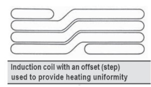
Stepping is easily accomplished by annealing the coil after winding and pressing it between two boards in a vise. The final effect is an even horizontal heating pattern versus a standard coil whose ends would extend above or below the main coil.

Flattened tubing creates a larger heating surface area for your coil. When using flattened tubing, coupling distance will be reduced and coil OD will be increased to reduce the spacing from the coil to the work piece.
Flattened tubing should be placed so that its larger dimension is adjacent to the workpiece.
Don’t see your induction heating issue on this list? Contact us for personalized assistance to improve heating uniformity and final part quality.

Objective Heat a customer supplied aluminum cylinder to 80-120°C for a material curing application. More application notes

In today’s manufacturing landscape, efficiency, precision, and sustainability are critical. Induction heating—a process that uses electromagnetic...

When it comes to many manufacturing processes, including this forging application, precision and efficiency are critical. Traditional heating methods...